
Just in case your search engine landed you here…other articles relating to this one are
Xiegu G90 & Digital Modes – What the Digital modes are about (focusing at the moment on FT8
Xiegu G90 & the CAT Cable – Where the CAT cable comes into play and how to build one if needed
Xiegu G90 & the CE-19 & Cabling – how to build the audio cables for the CE19 (You are here)
XIEGU G90 & FT8 – using the WSJT-X software and the Xiegu G90 to receive FT8
Overview
By now, you have you Xiegu G90 up and running, and you are reasonably familiar with it. You have pulled out the CE-19 you bought to setup Digital Modes and you have looked at all the cables that they have supplied.
This is what we are going to need
- 1 x Xiegu G90 Transceiver
- 1 x CAT Cable (came with and inside the G90 Box)
- 1 x CE-19 (this is an optional unit – but like many, you might have ordered it with the G90)
- 1 x 3.5mm Y Cable (yes you may need to make this up from the parts)
The last item, the 3.5mm Y Cable can be made from the following
- 3 x 3.5mm ended cables with tinned wire ends on one end of each of the cables. (which cam with the CE-19
or
- 2 x 3.5mm plug (TRS) ended cables with Tinned wire ends on the end of each of the cables
- 1 x 3.5mm TRS (Stereo) plug to 3.5mm TRS (Stereo) plug Audio Lead from local hardware or electronics store
The Y Cable
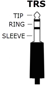
First of all, if you have not done a lot of soldering, particularly of audio style connections, you need to bring yourself across some nomenclature that is used particularly for the connections for the CE-19 / Computer Sound ports. You would have seen that I mentioned TRS, which stands for Tip / Ring / Sleeve. A four pole connector is TRRS (Tip / RIng / Ring / Sleeve), but we have no need for a TRRS plug.
Now I decided to start with a cable that I already owned, so it saved me a bit of fiddly connector soldering. So the cable shown in the next picture is what I started with (although I am showing it shortened for the picture.
Let me be clear, you do not need to buy or find a cable like the one below, but I suspect you probably have a few around the house. If you havent, then you can use the three cables with single plugs on them and follow the same principles.
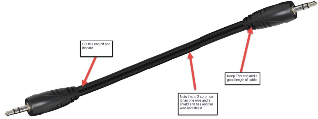
What we are doing is creating a Stereo Y adaptor however the two other ends, are still stereo jacks, but wired in a mono arrangement. Whilst I probably haven’t done a great job on the diagram, the shields are all common (usually the black wire marked as (1), and also known as the sleeve on the TRS plug.
The main thing is the connectors that will go into your computer/soundcard, the tip and the ring are joined together for both the microphone (AF in) and the speaker (AF out)
Now one more think. I am not sure how common the colours are in the cable I modified, but hopefully the numbering of the CE-19 end, will allow you to use a multimeter and confirm you have it wired correctly. In fact I recommend not using the colours as a guide, and stick with a multimeter, pen and paper, drawing it out so that you don’t make mistakes
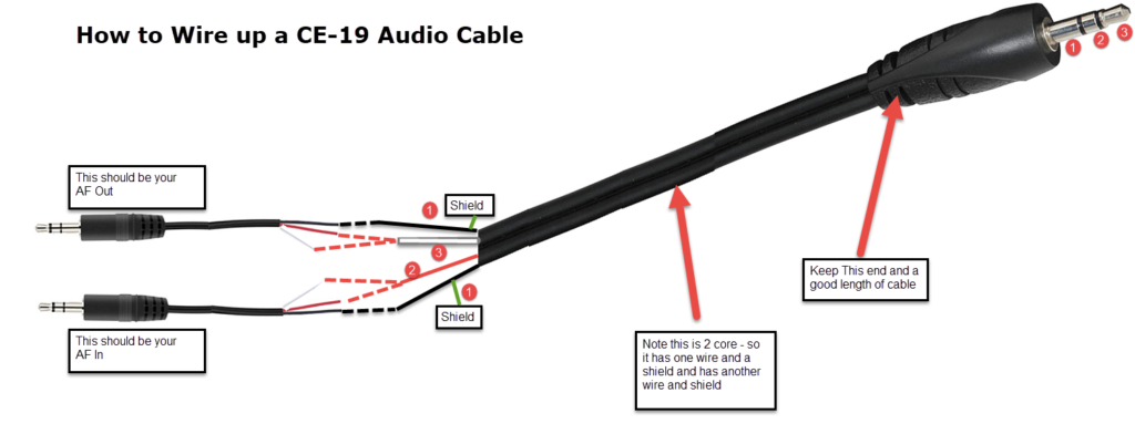
Now hopefully that is clear as mud…..but to make it easier if you have a multimeter. The following should true if this cable has been wired correctly. When I refer to the main plug, I refer to the larger plug in the picture above.
Put your multimeter into Continuity Sound mode
- Place a probe on the main plug (SLEEVE-1) and place the other on AF OUT sleeve. You should here a beep
- Place a probe on the main plug (SLEEVE-1) and place the other on AF IN sleeve. You should here a beep
- Place a probe on the main plug (RING – 2) and place the probe on both AF IN RING & TIP, Both should show continuity.
- Place a probe on the main plug (TIP – 3) and place the probe on both AF OUT RING & TIP, Both should show continuity.
- Now that you have determined the AF OUT – Mark it….so you don’t get confused.
- Ideally you should go back and check that you don’t get continuity when you shouldn’t, but if you feel confident, then that’s up to you.
Once you have the completed cable, the main things to remember is
AF IN – Connects to the Headphone Jack of your USB Sound Card or your Computer
AF OUT – Connects to your Microphone Jack of your USB Sound Card or Computer
To save you trouble, if you have coloured heatshrink, put the RED on AF OUT and Green on the AF-IN
Now to Test your Audio Cable with WSJT-X
Other than testing with a multimeter, the only real way to test your cable and interface is to use it in real life.
Connecting the CAT Cable
Now with your Xiegu G90, it came with a cable, which will be described as a XIEGU USB-TTL cable or a XIEGU Data Cable or Programming cable. Besides these names, you will also see it described as the G90 Cat Cable (interface). If you have read the previous articles, you will remember that mine arrived not working and had to build a new one (which, by the way, is working well).
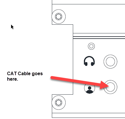
One end of this cable has a USB plug on it, and the other end has a 3.5mm TRS plug on it. If you have not figured it out yet, the USB goes into your computer (at least the computer that is using the WSJT-X and FL-RIG software. The other end (3.5mm plug, plugs into the side of the G90 as shown below
So I recommend going onto the next section – XIEGU G90 & FT8

Great, I’ve built the cable, tested the continuity, everything checks out, but where does the cable plug into the CE-19 and what do I need to plug into it to connect to my PC and Radio??? No one ever mentions this step.
Plasmastorm73,
The Y-Audio Cable that you built, the two ends go into your soundcard (input and output) on your computer, or in my case, I decided to get a slightly better sound interface by buying the SoundBlaster USB device.
The other end of that cable, plugs into the CE19 AF CON port. The CE19 X5105 Port connects to the Xeigu G90, the cable only plugs into one place on the G90 and the CE19.
I am assuming that this is the cables you are referring to.
Regards Bob.
Thanks! I appreciate you taking the time to reply. That is the cable I was referring to.
Plasmastorm73,
No problems, apologies on the delay in the initial reply. Due to some recent changes to the website, my comment notification ended up in my Junk mail (now resolved).
Regards
Bob