
| Hardware | Raspberry Pi 4 Model B (2Gb) |
| Operating System | Raspbian GNU/Linux 10 (buster) |
| Language | Python 3 |
| RPi.GPIO Revision | 3 |
| GPIO Interace | GPIO4 |
| Linux Device | N/A |
| Parts needed | Raspberry PI, Breadboard, Jumpers, Logic Analyzer, KY001 board or DS18B20 |
| Date Last Revised | 1st March February 2020 |
| Changes Made | Completely revised (& tested) for Pi 4 and Python 3 |
| | |
| Learning Outcomes | Setup of a 1-Wire Device, Use of Logic Analyzer, Use of Triggers and Logic Signal Analysis |
Our third tutorial is utilising the 1-Wire Protocol to talk to a low cost Digital Temperature Sensor via the GPIO. A very simple project and we are keeping it simple so that we can understand what we are looking at when we use a logic analyzer on a 1-Wire connected device.
We originally started this tutorial off with a DHT11 Temperature and Humidity Sensor. However, like many others, I found a huge issue with stability on this component, and based on what I read, I am definitely not alone with this issue. I spent a while trying to debug it, which included using different libraries in C, Python, adding a capacitor, trying a 5V supply, basically everything in my arsenal, but it would not provide reliable traces with the Logic Analyzer. Interestingly, the tell tale sign was the same setup and connections were used for the KY001 board or DS18B20 device, and with a few changed lines of code (including the library, to match the device, rock solid temperature readings, and perfect textbook traces for a 1Wire device.
So if you have a DHT11, and you are having issues, then don’t despair, you are not the only one, and one user even when as far to use statistics to simulate a more consistent result from a DHT11. These devices are supposed to be passed via quality control testing/calibration, but based on the writings on the Web, it seems that these devices, particularly coming from China are probably not Quality Control checked, or they failed it.
Anyhow, the work is not wasted. I have put the Tutorial aside, replaced it with this one, and will pull it out again, looking at the faulty DHT11 with an Oscilloscope.
Schematic

and for the more visually inclined, the breadboard looks as follows
Breadboard Diagram

Now for the code – Just scrape the code and save as a file. You can see the filename I have used, but you can make it shorter, just remember the .py extension.
The Prerequisites
You need into install the w1thermsensor library which you do at the linux command line
sudo pip3 install w1thermsensor
or
sudo apt-get install python3-w1thermsensor
Ok, let’s explain the two lines mentioned above, as this is the first time that we are loading a library that may not be included with the Raspian distribution.
Lets look at the first line. If you have not come across PIP before, you will find that it is already part of your Python install which is part your Raspian Operating system. Pip is a package manager for Python which allows you to install additional libraries and packages that are not part of the standard Python library
The developer when, they were satisfied with their code, would have packaged their code and submitted it to the the PIP repository, so that you can always get the latest released version.
Lets look at the second command line. This performs the same function, except it obtains it from the Raspian provided respositories, which is different to the PIP repositories. I prefer to use the PIP repositories, and I will normally visit the authors pages on those services to obtain up to date documentation and issues e.g. https://pypi.org/project/w1thermsensor/
Either command line will work.
Finally you will need the following line added to your /boot/config.txt at the end.
dtoverlay=w1-gpio
Alternatively, if you want to use the raspi-config GUI, just go into that and enable the 1-Wire interface, it will perform the same task. I mentioned before, that you are better off learning how to make these manual changes yourself, as it offers a lot more flexibility, for instance, you can change the pin that is used for the 1-Wire connection, which you cannot do via the raspi-config gui.
Finally, what ever methods you chose to complete the pre-requisites, you now need to reboot your Raspberry Pi before you run the code.
Show how 1 wire bus works with each device having a number
Show how we can change the ID to choose which one to read
Show 1Wire logic trace
Show how to implement triggers (can it be done on cheap or not)
Change Diagrams / Change Schematic
Show how to look at different libraries to achieve the outcome and benefits of one over the other.
The Code
#!/usr/bin/env python3
#####################################################################################
# Filename    : LogicAnalyzer_1Wire_Temp.py
# Description : Logic_Analyzer_With_1Wire Temperature_Sensor
# Author      : Bob Fryer / Digital Shack
# modification: 23 Feb 2020
#####################################################################################

#####################################################################################
# Import the required Python Libraries
#####################################################################################

import time
from w1thermsensor import W1ThermSensor

#####################################################################################
# Create and instance called sensor
#####################################################################################

sensor = W1ThermSensor()

#####################################################################################
# Define our main task
#####################################################################################

def readtemp():
# this  routine will run once...if you want it to loop remove the # on the next line.
#while True:
        temperature = sensor.get_temperature()                 # perform read of temp
        print("The temperature is %s celsius" % temperature)   # print on screen
        time.sleep(1)                                          # wait 1 sec - start again

#####################################################################################
# Define our DESTROY Function
#####################################################################################

def destroy():
    return
#####################################################################################
# Finally the code for the MAIN program
#####################################################################################

 if __name__ == '__main__':                                   # Program entry point
    try:
        readtemp()                                           # call readtemp function
    except KeyboardInterrupt:                                # Watches for Ctrl-C
        destroy()                                            # call destroy function
    finally:
        destroy()                                            # call destroy function
Now we are ready to run the code.
Now you should see something similar to this. Note I ran the command manually several times one after the other. The minimum amount of time that the device needs to settle is 1 second. I have already incorporated the 1 second delay into the code, so as soon as it completes you can run again.
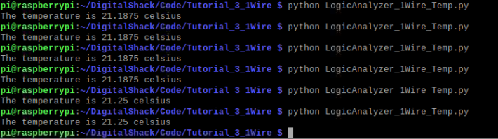
If you look at the code, there is a remark (comment) in front of a While instruction, if you remove this it will run in a loop. I have have commented it for the moment, so we can look a this with a Logic Analyzer looking at a single transaction.
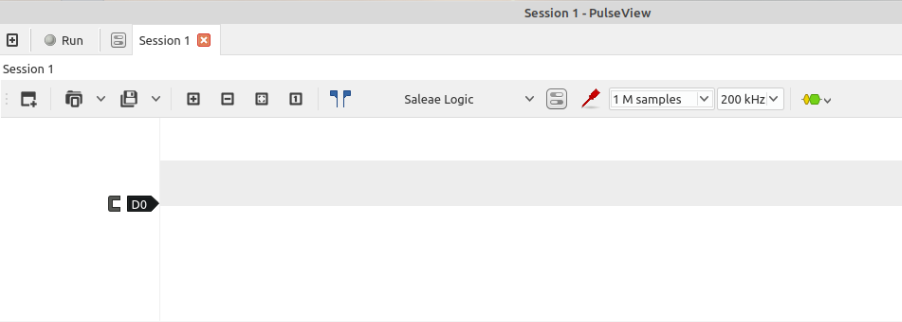
Connect the Logic Analyzer
Now if that is all working, now we hook up our logic analyzer (as shown on the breadboard diagram)
We are going to do something different here, even though it is not warranted, we are going to use a Trigger, so that we can commence capturing as the data starts or in our case just before.
After a bit of research on the 1-Wire protocol we come up with some dot points which we can use and they are :
- Typically 16.3Khz or can be in “turbo” mode (about 10x faster)
- Uses a pull up resistor to pull the wire up to 3 or 5 Volts
- Communication occurs when a master or slave briefly pulls the bus low
- The Master starts the transmission by pulling the wire to 0V for at least 480us. This causes a reset on every slave device.
- The Slave device(s) shows its “presence” by holding the bus low for at least 60us
- Each Slave has a unique identfier number, so these devices can be connected to a common bus and addressed by the master.
- Goes through several defined modes of communication, with the last transmission containing the data.
Before we get started, I am going to link to a specification sheet which should always be your first port of call as you work through possible issues. The first one is the Data sheet from Maxim, which is very comprehensive, and I do recommend you look for others
https://datasheets.maximintegrated.com/en/ds/DS18B20.pdf
Of particular interest to me when I read the document, was to confirm my timings were in tolerance, and secondly to have an undertstanding of the data flow, who’s transmitting what to who, and confirmation I was getting this.
So we start with the setup of Pulseview using what is most likely the highest possible data rate which is 200Khz, and working on the minimum sampling rate of 4x, we will use the 1M Sample rate. So setup Pulseview with these details and setup for 1 Channel like the example below
Now we move to the icon right at the end (the yellow and green waveform) and select a decoder which in this case is the 1-Wire Link Layer and you will see the same as below.

Now click on the Red labelled – 1 Wire Link Layer, so that we can bind it to the D0 channel as shown in point 1 in the picture below
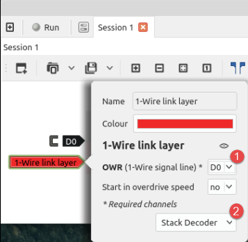
Before you finish, we are going to throw another decoder on the stack, which will be the 1-Wire Network Layer. So we end up looking like this picture below

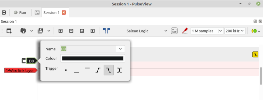
Now as mentioned previously, I said that we are going to use a simple Trigger in this Tutorial. There is very little reason to do so, but when you are doing the basics, this is the best time to use features and get used to them, and understand them.
So one thing we learnt from our research on 1Wire protocol was that in its idle state, the bus is held high, until transmission starts. So what we can do is set a trigger that “triggers” when the bus transitions from high to low. This means it starts recording when this condition occurs.
So, to set this trigger click on D0 and select the high to low transition trigger as shown in the image below
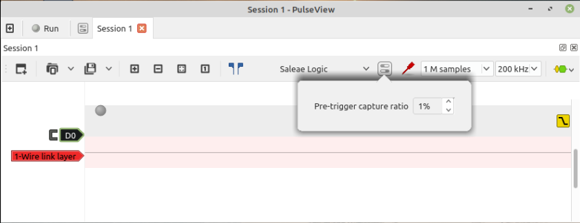
One more feature in relation to the trigger we can use, is the ability to choose to capture for a preset time before the trigger activates and to do that we select the icon as show in image below
Now we are setup, we can now commence our capture. So click on the Run at the top of the window. Don’t panic, you have time to go an run your code, it will not start capturing until it sees the transition of the bus go from high to low.
When you are finished, if it has not stopped, you can click on stop. You should end up with something simlar to below
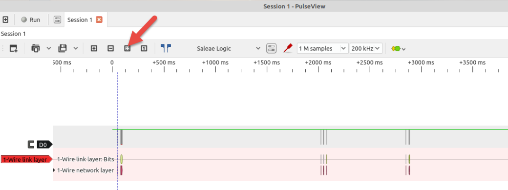
If it doesn’t, click on the icon shown by the arrow which is “Zoom To Fit” which will bring you capture into the one window. It won’t look like much, but we can now zoom onto the area we want. Note you can do that by pointing your mouse and clicking multiple times to zoom. In the example below, I clicked multiple times on the dashed blue line. That dashed blue line is actually your trigger activation shown.
Now you are starting to see some data, and if you notice, even though your trigger line is showing, it is actually showing the data before the trigger activated as we preset.
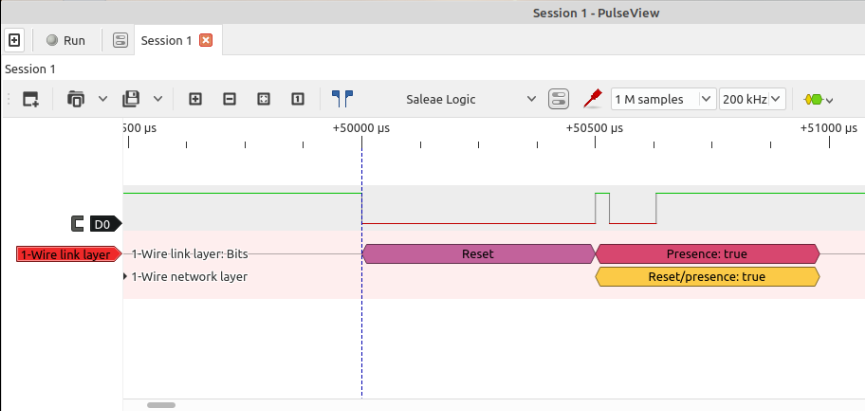
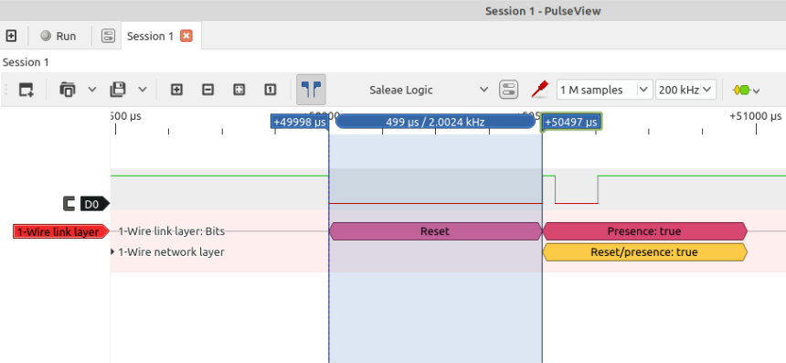
Now we can look at our capture and confirm that we have a properly working 1Wire device. As you can see, the first part is the master needs to pull the wire low for at least 480us. If we look at the measurements it pulls it low for 499us…That matches.
If we look at the next part of the capture, we will note that the bus is pulled low. As it states the Slave responds by pulling the bus low for at least 60us and as you can see below we have a measurement of 100us, which matches.

I won’t go much further in depth here as breaking the whole thing down is another whole new level and worthy of another article or multiple page datasheet. Besides, this is where the enjoyment in Electronics is, correlating a manufacturers data sheet and confirming that the hardware is working correctly, and whether your software or software library that has it wrong, or whether you have too much noise on the line to the temperature sensor, or whether you have too much attenuation due to the type of cable or length of cable you are using to the slave device.
However, when you capture your transmission, you should have something similar to below and after all the Master and Slave transactions, you should see a data packet at the end.
If you zoom in the this packet, you will see, something similar to below. I point to the 0xbe, as this is clearly stated as part of the transmission as per the Data Specification (towards the end of the Maxim specification sheet), it then states we should have 9 Bytes of data, which exactly correlates to what we have captured. Its now a case of understanding how that data is presented, and again, it will be clearly laid out in the Maxim Specification sheet.
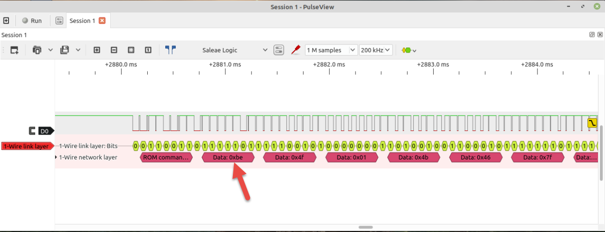
Even though we have skipped a few steps, it is worth reading the specification sheet, and understand the entire process. In the specification sheet, it will tell you when the master is transmitting and when it is receiving as this is one of the most common struggles when working with single line buses.
Notes :
Reading from Multiple 1-Wire Devices
As mentioned in the article, all one wire devices are programmed with a unique code. When you put multiple devices on the same bus, there are changes to the code to directly address the device. You can find more on library developers main W1Thermsensor page:-https://pypi.org/project/w1thermsensor/
