| Hardware | Raspberry Pi 4 Model B (2Gb) |
| Operating System | Raspbian GNU/Linux 10 (buster) |
| Language | Python 3 |
| RPi.GPIO Revision | 3 |
| GPIO Interace | 5V (pin 2), GND(pin 14), GPIO2(SDA1), GPIO3(SCL1) |
| Linux Device | |
| Parts needed | Raspberry PI, Breadboard, Jumpers, LCD1602 Display, Logic Analyzer |
| Date Last Revised | 4th June 2020 |
| Changes Made | Completely revised (& tested) for Pi 4 and Python 3 |
| | |
| Learning Outcomes | Setup and use a LCD display using I2C, Enable the I2C Service via GUI or Config file, Utilise a Logic Analyzer to view I2C transmissions |
This tutorial is utilising the I2C interface on the GPIO. This one whilst still simple (in terms of the user setup), actually is useful in as it forms the basis for many other projects, but will provide a platform so that we can understand what we are looking at when we use a logic analyzer with an I2C bus. The i2c bus is a serial bus, developed by Philips Semiconductor in 1982. More information can be found here: https://en.wikipedia.org/wiki/I%C2%B2C
Before we move on, it should be noted that when you see an advertisement for the LCD1602, you need to determine whether it is the base LCD1602 or the i2c version of the LCD1602 which has a daughter board attached to the display which does the i2c interfacing.

Now if you cannot get this model (which is about $US5-$US10), you can still use the standard LCD1602, but you will be using a lot more of your GPIO ports. As this article is discussing the use of the i2c bus, we will stick with this model of LCD1602. I may discuss the other model in a later article, especially if we demonstrate the use of Logic Analyzer on that model.
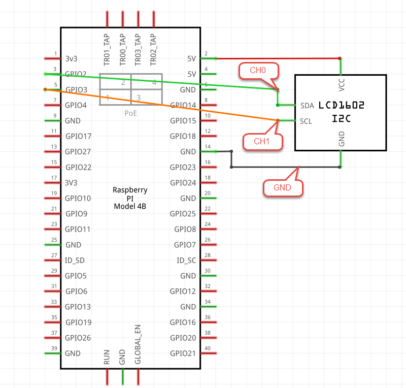
The circuit is quick to put together with the use of just four wires, which include 5V, GND, SCL1, SDA1. SCL1 being your clock, and SDA being the data connection.
Schematic
and for the more visually inclined, the breadboard looks as follows
Breadboard Diagram

Now for the code – Just scrape the code and save as a file. You can see the filename I have used, but you can make it shorter, just remember the .py extension.
The Code
Important Preparation
Before running this code, you need to make some changes to the O/S Startup.
You can either do this through raspi-config if you are a GUI sort of person, or you can edit the file directly (which honestly is a better way to go). GUI’s have their place, but they hide some of the critical understandings if what is actually happening, and in some cases have a negative impact.
So if you are using raspi-config, you need to issue the following command :
sudo raspi-config
Your menu will appear, select 5 Interfacing options, then select P5 I2C, you will get the following screen :

Select Yes, which will enable it and you should see the next screen confirming that you have enabled it.

Click OK, and on the main menu click on Finish which will drop you to the Linux prompt.
As these are changes to the boot config files which are read at boot time, you need to reboot for the settings to be applied.
If you want to make the modifications manually, then using your favourite editor (nano or vi or similar) modify the following file
/boot/config.txt (as I use nano the command line is nano /boot/config.txt )
This will open up the file with a wide range of settings, but the one we are looking for is dtparam=i2c_arm=on, check it is not there already, and if is not then add it. You will normally find it just under the arm-freq= line with a few other dtparam configuration lines.
It is worth reading the documentation http://rpf.io/config.txt , its a bit to get through, and honestly its more about making yourself aware of whats there, than learning it in its entirety. One more thing, you have made modifications of the boot config files which are read at boot time. So you need to remember to reboot.
Now having said all that about GUI’s and editing the file directly, if you feel more comfortable with the GUI to enable and change services, then go for it, but look for the changes it makes in the config files so you have a better understanding and indeed more confidence of what has been set.
Now we need to perform a few other commands
sudo pip install smbus
This command installs the smbus library. This library manages some of the lower level code of dealing with a bus using addresses and registers, as the i2c can have multiple devices on the bus
sudo pip install RPLCD
This command installs the RPLDCD library, which utilises the smbus library, and naturally contains the commands we use in our higher level Python application.
If you need clarification on this concept look at the following diagram to visualise it a little better.
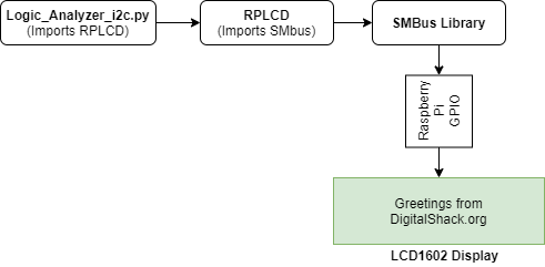
It is one of the areas that new Python programmers have a little trouble grasping, particularly as we step away from the “follow the bouncing ball” approach where you are provided a set of libraries to install (or have them pre-installed).
There is absolutely nothing wrong with this approach except when you follow a guide or tutorial and find that the library no longer exists (which is a common occurrence), or is no longer maintained, and new features have been added to the new device you are connecting to, or the device was retired and you are now dealing with a new device that doesn’t work exactly the same as the old device.
I fully recommend reading the Using Library’s Tutorial on this website to get a more detailed understanding of library’s and how to look for the correct library’s
Finally we have on more command, to type. This may already be installed on your Raspian O/S, but there is no harm in typing the command
sudo apt install i2c-tools
We need these tools so that we can identify what the i2c bus address that has been assigned to the i2c LCD1602.
Once it is installed, and you have the LCD1602 connected, you need to issue the following command
sudo i2cdetect -y 1
What you should get is a screen very similar to the following

In my case, the address is 3f, or to put it correctly 0x3f.
Now before you execute the code below, you need to take note of the bus address when you perform an i2cdetect, and you need to confirm the i2c chipset being used. If it is the generic run of the mill LCD1602 with i2c interface, then it is highly likely to be the PCF8574. This library supports the PCF8574, MCP23008, MCP23017 chips. Both the bus address you identified above and the chipset need to be confirmed or updated in the code below where it says Initialise the LCD instance.
The Code
#!/usr/bin/env python3
#####################################################################################
# Filename    : LogicAnalyzer_i2c.py
# Description : Logic_Analyzer_With_i2c
# Author      : Bob Fryer / Digital Shack
# modification: 22 Feb 2020
#####################################################################################

#####################################################################################
# Import the required Python Libraries
#####################################################################################

from RPLCD.i2c import CharLCD                         # Import CharLCD from RPLCD.i2c
import time                                           # Import Time Library

#####################################################################################
# Initialise the LCD instance with parameters - the i2c and the bus address
#####################################################################################

lcd = CharLCD('PCF8574', 0x3f)   # parameters as per the library and our bus address
                                 # you need to make sure these parameters match yours

#####################################################################################
# Define our main task
#####################################################################################

def flashgreeting():
    while(True):                  #loop - remove this line if you want a single pass
        lcd.write_string('Greetings!! from\r\nDigitalShack.org')      #write to LCD
        time.sleep(2)                                                 #sleep 2 secs
        lcd.clear()                                                   #clear display
        time.sleep(1)                                                 #sleep 1 sec

#####################################################################################
# Define our DESTROY Function & clean up routines
#####################################################################################

def destroy():
    lcd.clear()                                                #clear display on end

#####################################################################################
# Finally the code for the MAIN program
#####################################################################################

if __name__ == "__main__":                                     #Program entry point
    try:
        flashgreeting()                                        #call main task
    except KeyboardInterrupt:                                  #watches for Ctrl-C
        destroy()                                              #call destroy function
    finally:
        destroy()                                              #call destroy function
Now you can run the code by issung the command
python Logic_Analyzer_i2c.py
So, if everything is working correctly you should see you LCD1602 come to life, and it should flash every few seconds.

Just a quick note, if you are seeing nothing on the LCD Screen. Check the potentiometer setting. This potentiometer is to vary the contrast of the display. If it is set incorrectly, you see no characters. It caught me out for a few minutes, whilst I went back and checked the code.
Further Detail
Now before we move forward and look to see what is captured with a Logic Analyser, it should be pointed out that we are not going to see any light bulb moments, not from the Logic Analyzer anyhow, as the data side of the transmission is not visually clear. It is decipherable, but not with just Logic Analyzer software and again way past this tutorial.
What is useful however is to do with the Library that we selected for this tutorial addition functionality that we can use (I will be honest, I selected it as it had this additional functionality).
One of the nice easter-eggs with this library is the test-suite. The test suite is a command line tool that you can run (after you have installed the library), that demonstrates some its capabilities as a library. There is a help for this command by typing rplcd-tests (at the linux prompt) which will provide options…to save you the time, these two commands I have used
rplcd-tests i2c testsuite expander=PCF8574 addr=3f cols=16 rows=2
Shows the flexibililty of the library as well as the code
rplcd-tests i2c show_charmap expander=PCF8574 addr=3f cols=16 rows=2
Shows the Characters that can be achieved on the display
The RPLCD library author has included lots of documentation with his library (including attributing earlier authors or organisations). If you look at the page https://pypi.org/project/RPLCD/ , you will find he has documented the features, and compatible devices, and has included some command line tools to explore the features of his library, which means you can add to your code, to perform a little more than display two lines.
Furthermore you can delve into his library (via the PiPI) website and look at the code he has implemented to perform each of these routines. You might want to display custom characters. It is as simple as looking at the testsuite_16x2.py file, and for instance to display the custom characters, this simple bit of code
    lcd.clear()
    happy = (0b00000, 0b01010, 0b01010, 0b00000, 0b10001, 0b10001, 0b01110, 0b00000)
    sad = (0b00000, 0b01010, 0b01010, 0b00000, 0b01110, 0b10001, 0b10001, 0b00000)
    lcd.create_char(0, sad)
    lcd.write_string('\x00')
    lcd.create_char(1, happy)
    lcd.write_string('\x01')
    time.sleep(20)
Will display a simple happy and sad face on the LCD display.
This was taken straight from his testsuite code, with the addition of a time.sleep command, and used it in the current code, I placed a # on the front of each line under the def flashgreeting() under the main task and added the code above.
If you are note sure how he came with the binary mapping for the faces, imaging the character being 5 x 8 box, which you simulate in an excel spreadsheet, making the ones a bright colour and the zeros a dark color (you can make excel colour them with conditional formatting based on whether they are a 1 or 0. You will note that the top two lines e.g. 00000 and 01010 match the code for the happy face, except to the need to prefix with 0b which represents binary (or base2) in Python. You can also find websites that can perform this for you such as https://omerk.github.io/lcdchargen/ but if I am doing more complex animations (I find it easier to do this in a spreadsheet to visualise a little easier)

Further more, you might read further in the code, you will see that there is a LCD backlight command – lcd.backlight = True, which with true or false can turn off the backlight. Typical examples of this is an temperature alarm panel, where you may want to flash the LCD panel to draw attention to it.
Understanding the library’s you are using is important and what their capabilities are. You must remember, that the author that writes the library will document somethings on a web page, other things are documented in the code, and some things may not be documented, which you can extract from the code.
Again I fully recommend the separate tutorial on this website, where we focus on library’s, how to use them, how to select a library, and how to get the most out of it. We have only started to touch on it in this tutorial.
Connect the Logic Analyzer
Now if that is all working, and you had a play with the library, put the code back to the way it was. Now we hook up our logic analyzer (as shown on the breadboard diagram). The main difference over the previous tutorials is that we are going to connect two channels and the ground to the Logic Analyzer
To make you analysis easier, I am also going to recommend that we stop the application looping, so that we can analyze a single write to the LCD Display. To do this, where I have remarked in the code, place a # in front of the line with the While(True): for a single pass.
So lets prepare pulseview, if you have gone through the previous tutorials, then you will know the routine, so I won’t spell it out too much, but you need the following settings

- Click on the probe icon and only select two channels
- Click on D0 and rename to sda
- Click on D1 and rename to scl
- Set 1M samples maintaining our 4x or better sampling rate
- Set 200Khz(as we know the default is 100Khz for i2c)
- Select i2c as the decoder
What you may find interesting is that you did not have to bind SCL to D1 or SDA to D0. As you named them the same as recognised i2c names, it automatically assigned them.

As you learnt in the earlier tutorials, you can setup a trigger. Again we know that it transitions from High to Low, and the first line that commences transmission is the sda line, but that is up to you if you want to use a trigger, and also want to set a 1% pre-trigger capture ratio. I find that I do it on a regular basis especially on faster transmissions e.g. greater than 100Khz
What you will capture will be similar to the following (after your zoom out)

The first thing I do is check the speed was what was expected.

As you can see above, we are almost spot on 100Khz. The reason why I do this (confirm speed) is to confirm the bandwidth is correct, and I am capturing enough samples to provide an accurate decode.
Finally, I now check to confirm that have now captured a valid i2c communication

One thing you can see immediately at the start of each data transmission is the Address of 3F (in the case above) and this is the address that I had to add to the code to correctly address the LCD unit.
Main things we are checking for are framing errors, or failed acknowledgements indicating issues. We will look at the i2c protocol in more detail in a later article, and indeed we will look further into confirming transmission to data to the LCD display.
Notes :
